Making a 25ps resolution Time-to-Digital converter on an Artix-7 FPGA
Published:
I want to share a small project I did in which a 25 ps Time-to-Digital converter is implemented in an Artix-7 FPGA. The goal was to be able to measure tiny intervals between singals from two photomultiplier tubes. Finally, a fast digitizer was better suited for the job, but nevertheless the TDC works well and could be useful.
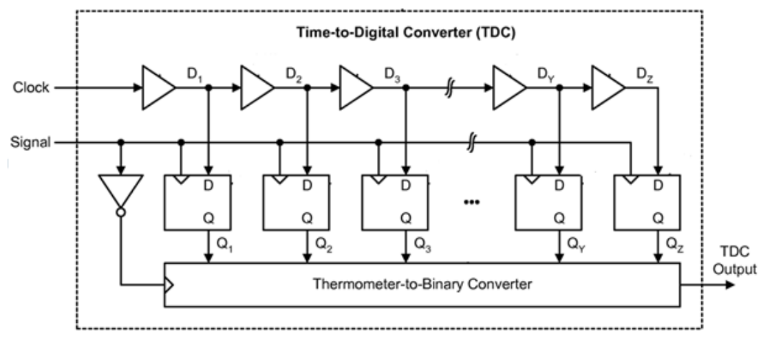
The board has two inputs for the signals that would trigger the start and stop of the TDC. The TDC itself is composed of two parts: a course counter with a 450 MHz clock and 2.22 ns timing resolution, and two delay lines with 104 shift registers for the fine measurement of the time between signal and clock. The shift registers lead to a timing resolution in the order of 25 ps. Keep in mind that this implementation is subject to a severe differential non-linearity, and, while not so difficult to do in VHDL, the trick is to place the shift registers in such a way as to balance the signal propagation times. A schematic of the delay line is shown in the next figure.
After the time to digital conversion takes place, the number is stored in a FIFO buffer. The buffer is periodically flushed through a UART interface to a computer. The incoming time intervals are then plotted by a python code that you can find on my Gitlab.
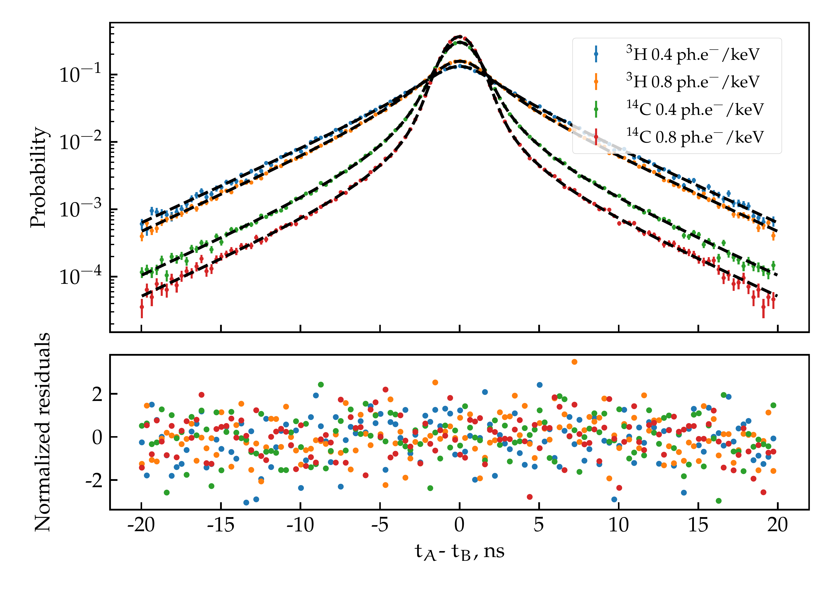
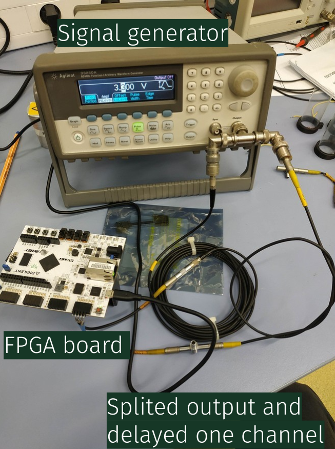
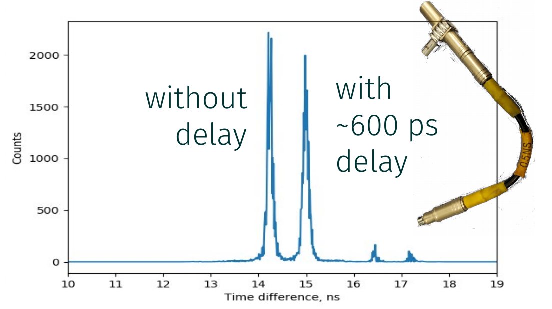
The device was tested with an Agilent 33250A signal generator. The output of the signal generator was splitted and one of the cables is a tiny bit longer than the others. On the second picture you can see the different spectra with ~600 ps delay line.
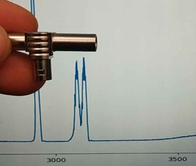
The TDC is quite sensitive because you can clearly see even the tiny propagation
time through this 2 cm LEMO connector!
The Vivado project and VHDL code can be found on my Gitlab. Everything is GPLv3, so you are free to use, modify and distribute it as you like.